1.6.1. Pi-Star
Pi-Star is a software image built initially for the Raspberry Pi (produced by the Raspberry Pi Foundation). The design concept is simple, provide the complex services and configuration for Digial Voice on Amateur radio in a way that makes it easily accessable to anyone just starting out, but make it configurable enough to be interesting for those of us who cant help but tinker.
1.6.1.1. Hardware
This short document shows you how to assemble the most basic Hotspot around – A Pi-star MMDVM device. This is constructed from two main boards – a Raspberry Pi single-board computer and an MMDVM Modem HAT.
Once constructed the Hotspot can then be configured using Pi-star software installed using a microSD card. This is dealt with in a separate note.
The Hotspot is very easy to put together and, at worst, needs only some header pins soldered to the Raspberry Pi board. If you don’t wish to do this then a version of the board is available with the header pins already fitted.
1.6.1.1.1. Sourcing the Parts
The best place to find the items needed is online; Ebay, Amazon etc. There are two main parts that you will need: A Raspberry Pi single board computer and an MMDVM HAT.
Any Raspberry Pi will do but the best fit is a Pi Zero -W. It is perhaps worth spending a little bit more to get the -WH version as this has the GPIO Header pins already soldered on. It must be a -W as you need the wi-fi for the internet connection. They may be slightly dearer but will be top quality if you buy from an official distributer. I buy mine from one of the UK suppliers (https://thepihut.com)
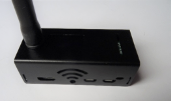
The MMDVM HAT is the modem / radio board. I prefer the ones with an on-board OLED Type 3 display. This allows you to see the hotspot is working without connecting to it over the local network with a browser. There are a large number of Chinese clones about and these are of variable quality. If possible, source the board from a UK supplier as it is easier to return faulty ones. The one I used for this document came complete with a case and aerial, pre-packaged in a box secured with Chinese tape. Presumably imported as a job lot and then resold. The leads for the display were too long and fouled the GPIO pins on the Pi. I simply cut them off but it did serve to show the build quality. Also, the board had absolutely no maker’s markings.
To make the hotspot work you also need a class10 microSD card. 8GB is more than big enough. Again, I source these from a UK suppler. You also need a microUSB lead to supply the power and possibly a 5volt 1amp USB power adapter. Get a lead designed to charge mobile phones as they have thicker conductors. There are inexpensive, official Raspberry Pi power supplies available.
The example shown here also came with a two-part metal case. This is a worthwhile addition but not essential. It all depends on where you are going to use the hotspot.
1.6.1.1.2. Assembling the parts
First gather the items together. This picture shows them laid out ready for assembly. The whole process takes less than 10 minutes! If you have brought the Pi Zero without the header pre-fitted you will need to solder in place the two sets of pins supplied with MMDVM board. These will need to be located either end of the row of connector holes.
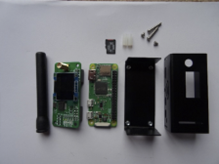
Left to right we have:
Aerial – comes with the MMDVM Board
MMDVM Board with display
Pi Zero-WH with microSD card
Two-part case with screws and spacers.
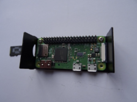
Step 1 – Fix the Pi Zero to the case base.
Make sure you fit the board the correct way around! The short slot in the case is for the microSD card, the longer slot is for a camera cable. It is easy to get it wrong.
Retain the board using the two short screws, one either end of the board adjacent to the 40-pin GPIO connector.
Don’t do the screws up too tight at this stage.
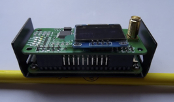
Step 2 – Mount the MMDVM Modem board.
This plugs onto the Pi GPIO Connector pins. It only fits one way around, just make sure it is properly located on all the pins.
Then, using the two spacers and the two longer screws, bolt through both boards into the base. Once all four screws are located, they can be tightened properly.
Remove the protective film on the display if there is one.
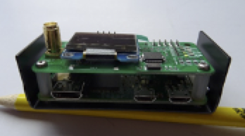
Step 3 – Fit the top part of the case.
This is the trickiest part of the whole process. The case is a friction fit and you need to ‘open’ the top part and ease it over the four mounting lugs on the bottom half end pieces. Make sure you get it the right way around – with the holes lining up with the various connectors on the Pi Zero board. You may find the case will need ‘adjusting’ with a small file to make the ports fit properly.
Finally screw on the aerial.
You now have an assembled Raspberry Pi based Hotspot. Simply insert the microSD card and power it up. Follow the instructions in the Software document and you should be up to speed in no time.
1.6.1.2. Software
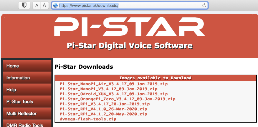
Downloading Pi-Star software https://www.pistar.uk/downloads/
Select the image for your system, typically using a Pi-Zero select
Pi-Star_RPi_V4.1.2_20-May-2020.zip
expand the zip file, inside will be a .img the file.
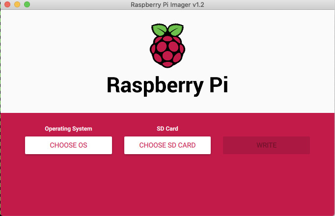
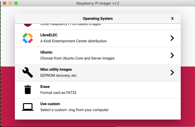
Download and install software to write the image to the micro SD card for example Raspberry Pi Imager
Select “Choose OS” and scroll down to “use Custom”.
Insert a SD card (16Gb is plenty of space) and select it and write the image. It should only take 5-10 minutes.
Once complete you can remove the SD card from the computer.
1.6.1.2.1. Set WiFi credentials
Insert the SD card into your computer and it should mount the BOOT partition. If you want only a single WiFi connection you can use the tool on the pistar.uk website (you can always add more once it is running) If you want more to start with then use a simple text editor, such as notepad, create a file called “wpa_supplicant.conf” which will define your WiFi. You can add multiple WIFI networks, e.g. mobile phone, home WiFi, office WiFi, etc. The Pi will then look and try to connect to each in turn. (Also see Auto AP in the Advanced Features section below)
Copy these lines to the new file “wpa_supplicant.conf” and save it to the SD card, (BOOT partition).
ctrl_interface=DIR=/var/run/wpa_supplicant GROUP=netdev
update_config=1
ap_scan=1
fast_reauth=1
country=GB

network={
  ssid="MY SSID"
  psk="My SUPER SECRET PASSWORD"
  id_str="0"
  priority=100
}
Each subsequent network should have a decreasing priority number, this is the order the Pi searches for networks.
Once written, eject the SD card and you’re ready to boot the Pi-Star.
Put the SD card into your pi-star and power it on. After a short time it should complete boot, you should be able to reach it with the URL http://pi-star.local. If not you might need to find it’s IP address. This can be easily done by logging into your internet router and looking at the list of DHCP leases.
1.6.1.2.2. Initial configuration
Connect to http://pi-star.local, and login with the credentials
username: pi-star
password: raspberry
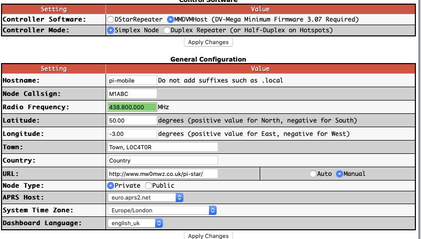
Work your way down the “General Configuration” settings.
Node Callsign
DMR ID
Radio Frequency, pick one that’s free where you plan to use it.
Location settings are optional.
Node Type, if set to private will only accept radios with your DMR-ID, make public if you have multiple, though rules suggest this might not be permissible in the UK. This can be overcome by Whitelisting DMRIDs.
Select apply changes. Once refreshed which can take a few seconds more config options will display
Before going much further set the radio/modem type to match your MMDVM modem (Identifying you MMDVM Modem) and select apply again. It’s often necessary to set this twice on first configuration.
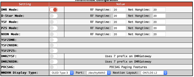
Enable DMR and select Apply.
Set the Display details if you have one.
Apply changes
1.6.1.2.3. DMR Configuration
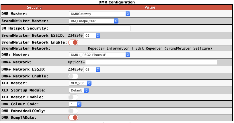
set DMR master to “DMRGateway”
Apply changes
We will start with the Brandmeister network. Set the BrandMeister Master: “BM_United_Kingdom_2341”, The is the UK one but others are available.
The ESSID can be left blank if you only have one Pi, but could be set to ‘01’. If you have multiple Hotspots make sure each is unique.
1.6.1.2.4. Brandmeister API key
The API key allows the pi-star hotspot to interact with brandmeister servers and set and unset static talk groups and reflectors from your admin dashboard.
You’ll need to create an account with Brandmeister, https://brandmeister.network, creating an account is straight forward and just requires for DMR-ID for validation.
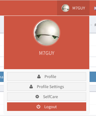
Once youre account is enabled, you can login and select “Profile Settings”,
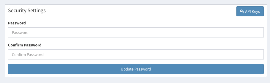
Under Security Settings, on the right hand side is a button “API Keys”, selecting this to manage your keys.
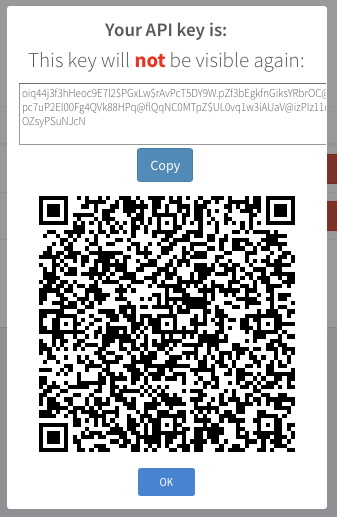
Select “Add” to create a new key, pick a name for the key. Not sure the value of the QR code, so just copy the string at the top, you can select the “Copy” button.
With it copied reconnect to your new Pi-star and select configuration, and then select “Expert”, you’re now looking for the button “BM API”. Click on this.
You can now paste this key into the field presented and select “apply changes” to finish. The Admin Dashboard will now have controls to allow you to edit Static Talkgroups on the Network.
1.6.1.2.5. Phoenix
An alternative network to Brandmeister is Phoenix. In the DMR Configuration section activate the DMR+ Master and select DMR+_ISPC2-PhoenixF from the list. As with the Brandmeister section add the ESSID, also “01” if it is your first Hotspot.
1.6.1.2.6. DMR Gateway
DMR Gateway allows you to connect to multiple DMR Networks at the same time but requires additional work; both in the Pi-star configuration and in the codeplug for your radio(s). This is to allow the Hotspot to determine which DMR Network you are trying to access from your radio. By default, almost all traffic will be routed over the Brandmeister Network.
1.6.1.2.7. Dashboards
There are two dashboards you can watch, “Dashboard” and “Admin”. The Dashboard provides a good overview of the pi-stars operation. The Admin board provides additional details on Brandmeister static talk groups, and with the API key set allows to add and remove them.
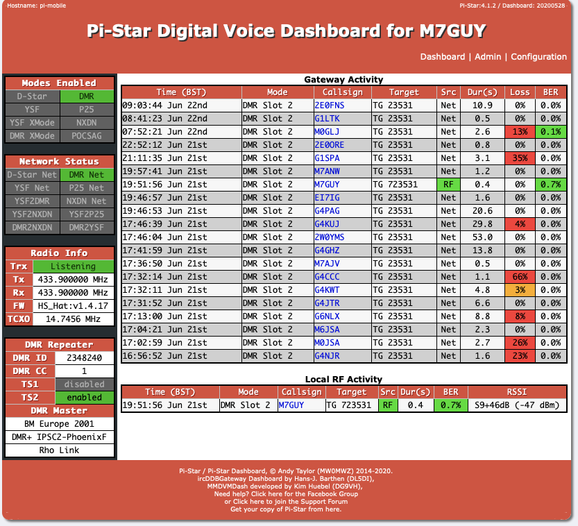
Fig. 1.4 Dashboard
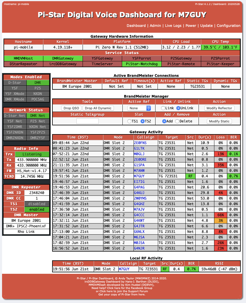
Fig. 1.5 Admin Dashboard
1.6.1.2.8. Advanced Features
There are many things the Pi-star software will do. It will, for instance, support other Digital modes, simultaneously if required but only one at a time! It can even form the basis of a Repeater using appropriate hardware. This section will include these as and when they are discovered.
Things like different display settings. If your MMDVM board has an OLED display you may find it upside down. In the main Configuration section, there is an Invert function which corrects this. You can also set a Scroll mode, set to 1 it gives a scrolling display on idle.
You can use “Configuration”, “Expert”, “CCS Tool” to change the colours of the Browser User Interface.
1.6.1.2.9. Auto AP
Use Auto AP when you start Pi-star for the first time without setting any WiFi credentials, or when you need to connect to a new WiFi network, for example, when traveling. When Pi-star doesn’t find a known network within about three minutes after power on, Auto AP will automatically activate its own access point, and you’ll use that to connect to Pi-star in order to configure WiFi settings.
Wait at least three minutes for Auto AP to activate its access point.
On a Windows, Mac, or Linux-based computer (not the hotspot itself) that has WiFi enabled, look in the WiFi settings to find the Pi-star access point, and then select it to connect to it:
If you’re starting Pi-star for the first time, it’ll be named “Pi-Star-Setup.” If this isn’t the first time, but you need to connect to a new WiFi network, it’ll be named using the Hotspot’s hostname, by default, “pi-star” (or whatever you changed it to in the General Configuration settings).
Enter the Pi-Star-Setup network security password: raspberry.
Once your device is connected to the Hotspot access point you can use a browser to login to the Pi-star using http://pi-star/, http://pi-star.local/ or 192.168.50.1 and make any required configuration changes. For instance, to set new WiFi credentials.
1.6.1.2.10. Identifying you MMDVM Modem
If you’re not sure which type/model of MMDVM modem you have then Pi-Star have provided a simple command to run to help determine it.
Login to the SSH prompt for your Pi-Star and issue the following command
sudo pistar-findmodem
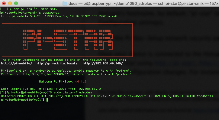
Note the details provided and match against the list of possible modems that are supported.
1.6.1.2.11. Using the Pi-Star MMDVMCAL Test programme
Pi-Star has a very useful built-in test programme for setting up and evaluating the hotspot hardware.
To fire it up first go to ‘Configuration/Expert/SSH Access’ in the Pi-Star dashboard. Log in using the appropriate Pi-Star login and password (by default pi-star and raspberry). You should then see this screen:
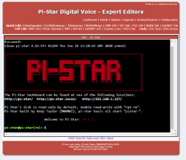
Type in the following command: sudo pistar-mmdvmcal
Eventually you should see the following list of commands:
H/h      Display help
Q/q      Quit
W/w      Enable/disable modem debug messages
E/e      Enter frequency (current: 433000000 Hz)
F        Increase frequency
f        Decrease frequency
Z/z      Enter frequency step
T        Increase deviation
t        Decrease deviation
P        Increase RF power
p        Decrease RF power
C/c      Carrier Only Mode
K/k      Set FM Deviation Mode
D/d      DMR Deviation Mode (Adjust for 2.75Khz Deviation)
M/m      DMR Simplex 1031 Hz Test Pattern (CC1 ID1 TG9)
K/k      BER Test Mode (FEC) for D-Star
b        BER Test Mode (FEC) for DMR Simplex (CC1)
B        BER Test Mode (1031 Hz Test Pattern) for DMR Simplex (CC1 ID1 TG9)
J        BER Test Mode (FEC) for YSF
j        BER Test Mode (FEC) for P25
n        BER Test Mode (FEC) for NXDN
g        POCSAG 600Hz Test Pattern
S/s      RSSI Mode
I/i      Interrupt Counter Mode
V/v      Display version of MMDVMCal
<space>  Toggle transmit
Firstly, use the E (or e) command to set your required test frequency in hertz (default is 433.000MHz) e.g. 434.9875MHz will go in as 434987500
The Spacebar toggles transmit ON/OFF.
The command C (or c) will transmit a carrier only for checking the transmit frequency error and RF power level. The frequency can be tuned while transmitting, using F to increase or f to decrease. The step size, in hertz, is set using the command Z (or z). Minimum step size is 10Hz. The frequency error, in hertz, can then be corrected in the ‘RXOffset’ and ‘TXOffset’ boxes in the ‘Modem’ section of ‘Configuration/Expert/MMDVMHost’. The RF power level can be adjusted, while transmitting, using P to increase and p to decrease. The power level is shown as a percentage of the maximum.
The command D (or d) is used to check/set the deviation level. The level can be adjusted, while transmitting, using T to increase or t to decrease. The correct value is 2.75kHz. The level is shown on the screen as a percentage. When you have found the correct value make a note of it as it is the value that goes into the ‘DMRTXLevel’ box in the ‘Modem’ section of ‘Configuration/Expert/MMDVMHost’. The default value is 50. If you have an SDR receiver then the deviation can be set very precisely by zooming in to the transmission on the SDR display so that you can see the carrier and the modulation sidebands. Then adjust the deviation level to null the carrier. If the theory behind this interests you then there is a very good explanation by F5UII at https://tinyurl.com/y2gs9xo9 .
The command M (or m) transmits a DMR Simplex 1031Hz Test Pattern on the test frequency to Colour Code 1, Radio ID 1 and Talkgroup 9. If all is well you should hear a smooth 1031Hz audio tone, with no glitches, from a receiving DMR radio. I can’t help thinking that this could be used as a reference signal for setting up microphone audio levels?
The command b can be used to check the DMR Bit Error Rate (BER) of the transmissions from the radio that you use to talk to the hotspot. B does the same for a DMR 1031Hz Test Pattern transmission (from another hotspot say). A YSF transmission can be checked for BER using the J command.
The command S (or s) displays the RSSI value of the RF signal that the hotspot is receiving.
The command W (or w) toggles the display of modem debug messages when transmitting from RF into the hotspot.
I haven’t been able to check out the P25, NXDN and D-Star functions.
The command ‘K/k Set FM Deviation Modes’ appears to be an error?
Commands that produce a continuous scrolling display (like RSSI Mode) can be cancelled by selecting another command.
If you are using the Pi-Star with a Digital Voice Modem (like the STM32-DVM) then there are extra commands for setting up the modulation/demodulation.
The command Q (or q) quits the test programme and puts the hotspot back to normal operation.
1.6.1.2.12. Fixing DMRGateway Issue (June 4-5th 2021)
Over the night of June 4-5th 2021. Pi-Star was updated with new versions of DMRGateway and MMDVMHost. This update has a miss configuration which can cause you hotspot not to connect to any DMR services.
Andy of Pi-Star is already fixing this and in the next auto update it should be corrected.
To correct this issue manually it quite straight forward.
Login into your Pi-Star, select “Configuration” and then “Expert”.
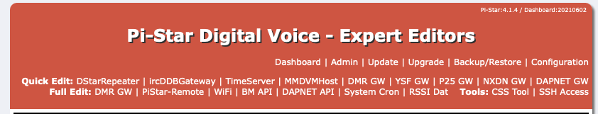
Select the “MMDVMHost” menu option. Scroll down to the “DMR Network” block.
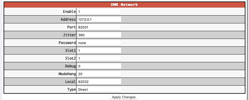
Look for the entry “Type”. At the moment this is set to “Direct”. This needs to be changed to “Gateway”. Once changed make sure to click on the “Apply Changes” button below this box. You should now be able to go back to the Dashboard and in a few seconds your connections to the DMR services should be restored.
You can confirm this by looking at the RAYNET DMR server dashboard and seeing your peer is now connected.